

What we do
Six services covering field capture, modeling, coordination, and verification.
3D Laser Scanning
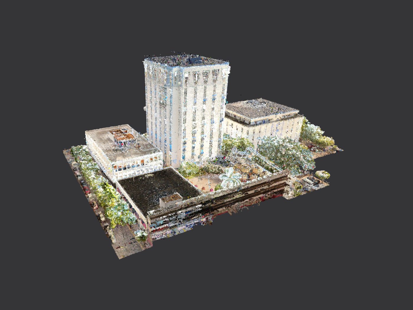
Laser scanners record millions of measured points per second, producing a dimensionally accurate record of a building or site as it stands today. Scans are registered together and tied to survey control so the whole data set lives in one coordinate system.
The registered point cloud becomes the reference every downstream deliverable is built from, which removes the guesswork that comes with outdated drawings.
- Registered point cloud
- Survey control
- RCP and E57 output
Construction Layout and HP SitePrint
Layout crews transfer coordinates from the coordinated model to the field with a robotic total station, marking hangers, embeds, sleeves, anchor points, and wall lines at their modeled positions.
The same instrument records as-installed positions and returns them to the model, which keeps the model and the building in agreement as work progresses.
- Model to field
- Robotic total station
- HP SitePrint
- Control networks
Scan-to-BIM
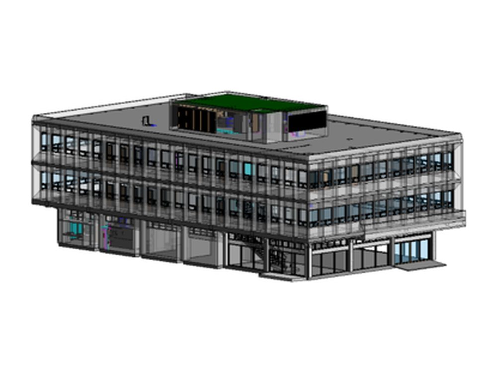
Scan-to-BIM converts a registered point cloud into an intelligent building model. Walls, floors, structure, and MEP systems are modeled as parametric elements rather than traced geometry, so the model carries data the project can query.
Scope is set by level of development. LOD 200 supports early planning, LOD 300 supports design and documentation, and LOD 350 or 400 supports coordination and fabrication.
- Revit deliverable
- LOD 200 to LOD 400
- As-built documentation
3D Modeling
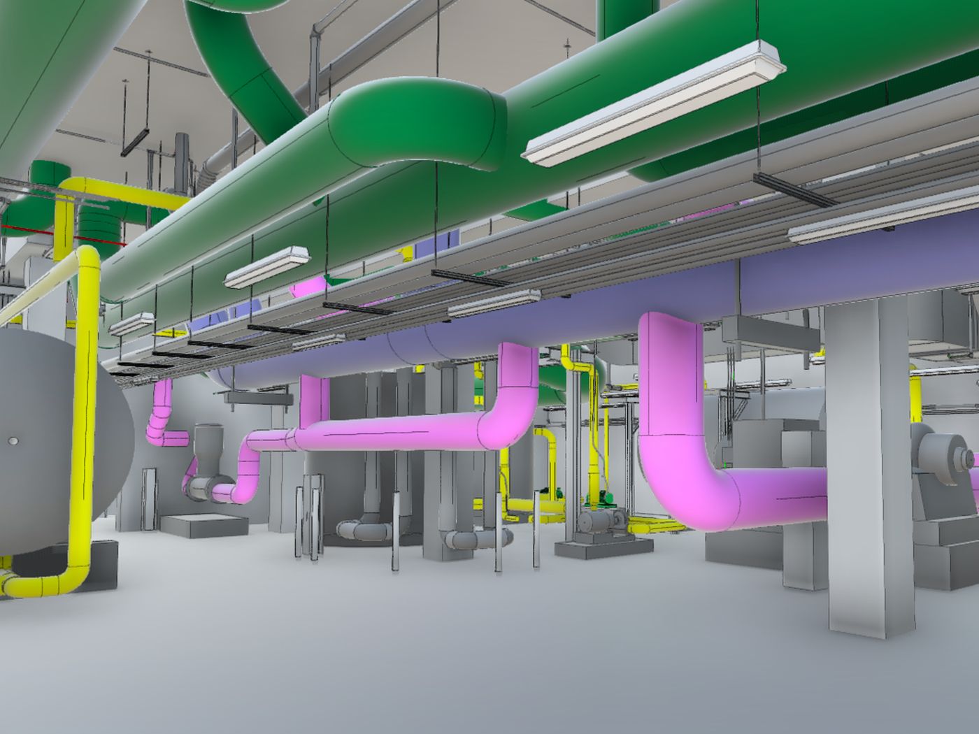
Architectural, structural, mechanical, electrical, plumbing, and fire protection models built to the standards your team already runs, including template, shared parameters, worksets, and naming conventions.
Fabrication level modeling carries the detail trades need to spool and order, including hanger locations, connection types, and real component geometry.
- Architectural and structural
- MEP and fire protection
- Fabrication detail
BIM Coordination
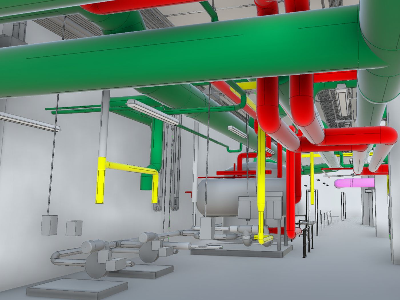
Trade models are federated into a single environment and run through clash detection. Each conflict is grouped, assigned, and tracked to resolution rather than dumped on the team as a raw clash report.
Coordination meetings work through the open issues on a set cadence, and sign off happens area by area so installation can start where the model is clear.
- Federated models
- Clash detection
- Issue tracking and sign off
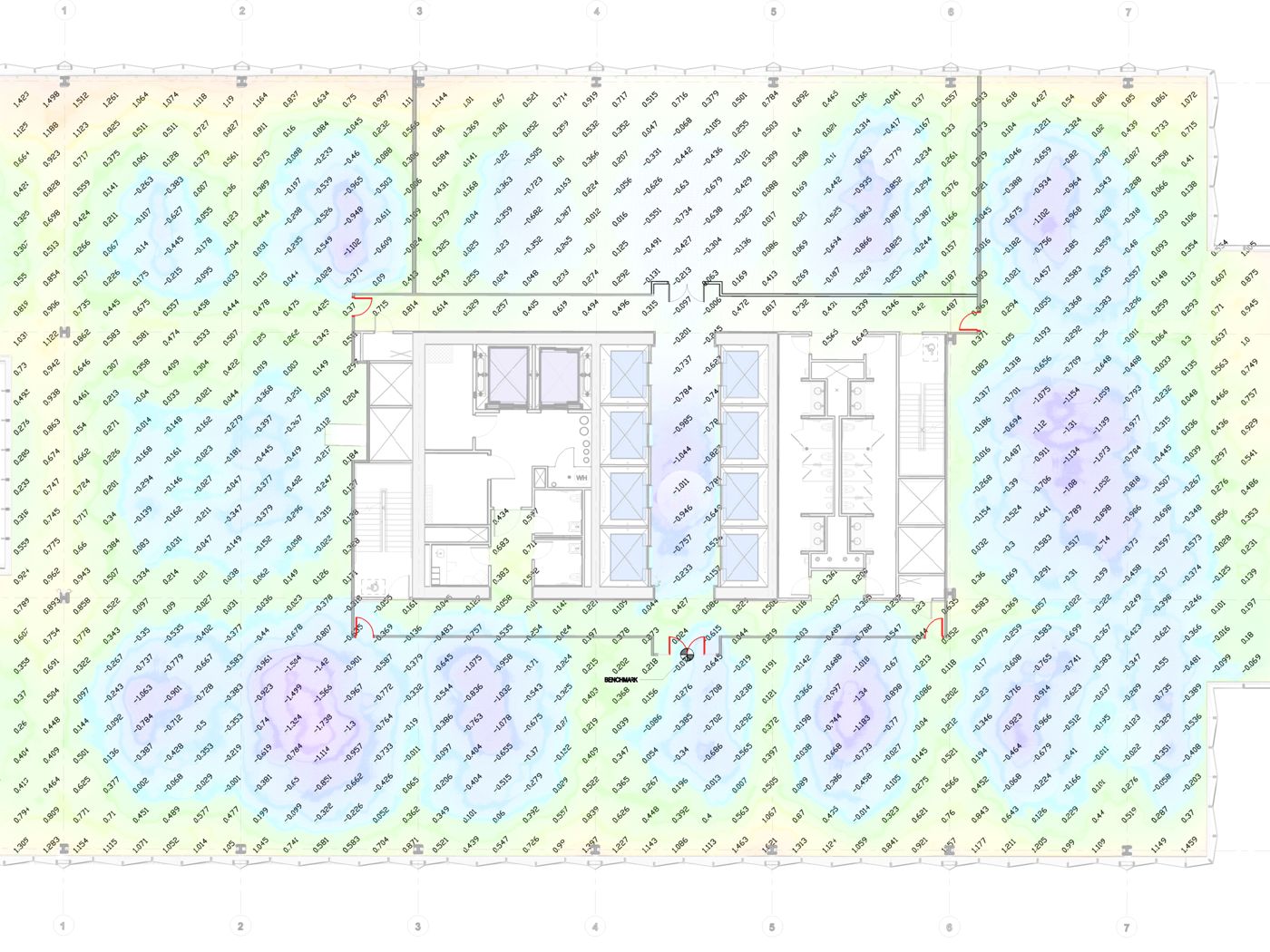
Analysis and Verification
Compare and verify installed work or existing conditions such as wall plumbness, floor flatness, design model versus as-built model and more.
Installed work is scanned and compared against the coordinated model. Deviation maps show where the building differs from design and by how much, in the same coordinate system the model uses.
- Deviation analysis
- Floor flatness and levelness
- Fit checks
Contact Us
Tell us the building, the scope, and the deliverable you need. We will come back with an approach and a number.
708-575-0335
information@innovationdc.net
11305 Distinctive Dr
Orland Park, IL 60467